This technical guide is continuously updated (last updated in May 2026) based on over 15 years of daily diagnostics and troubleshooting of offset presses (including Heidelberg, Komori and Manroland systems).
All solutions have been tested in real printing and packaging plants to reduce paper waste and optimize water and ink balance.
How Do You Identify and Eliminate Hickeys (Spots and Halos) on an Offset Printing Press?
In high-speed offset lithography, a hickey is one of the most persistent print defects that directly impacts pressroom efficiency and macro-level paper waste.
Based on over 15 years of pressroom troubleshooting, managing hickeys requires understanding whether the contamination is ink-borne, substrate-borne, or environmentally driven.
As we previously emphasized if they are left uncontrolled, they cause us massive amounts of waste.
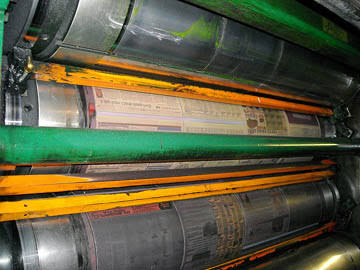
Source: Stumptown Printers
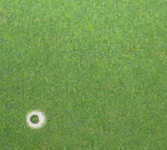
Visually, a hickey manifests in two distinct shapes: a solid dark speck surrounded by an unprinted white halo (often called a “donut” hickey, typically caused by ink skin or particles adhered to the plate or blanket) or an unprinted white void within a solid print area (usually caused by loose paper fibers or dust blocking the ink transfer).
Offset Hickey Causes & Immediate Pressroom Remedies
| Defect Manifestation | Primary Root Cause | Immediate Pressroom Corrective Action |
| Donut Spots (Speck with white halo) | Dried ink skin in the fountain or unground pigment aggregates. | Stop the press, apply adhesive tape to the blanket to pull and inspect the particle, scrape the fountain, and install an ink-fountain screen. |
| White Voids (Unprinted fibers) | Paper linting, surface picking, or slitter dust from low-quality stock. | Wash blankets, reduce ink tack by adding 2% to 3% of a compatible tack-reducing gel/varnish, and check feeder dust-brushes. |
| Irregular Repetitive Specks | Degradation of elastomer composition on ink form rollers. | Inspect roller geometry and stripe width. Replace glazed or pitting rollers showing hardness outside the 25–30 Shore A specification. |
Deep-Dive Troubleshooting: Advanced Root Causes & Press Adjustments
Ink-Borne Contamination & Fountain Hygiene
The most common cause of a hard-particle hickey is dried ink skin forming in the ink fountain or an open can.
When the ink knife scrapes the container incorrectly, these oxidized fragments enter the ink train.
To solve this, operators must thoroughly dip out the fountain.
For critical solid-density jobs, running the ink through a fine mesh strainer before loading is highly recommended.
Substrate Picking and Ink Tack Dynamics
If the surface strength of the paper (measured via IGT pick resistance) is lower than the split-tack force of the ink, the ink will literally rip fibers and coatings off the sheet.
These fibers stick to the tacky blanket, creating repetitive voids.
The Fix:Carefully adjust the rheological properties of the ink.
Introduce a maximum of 2% to 3% reducing oil or let-down varnish to lower the ink’s tack value without destroying its structural body or lithographic water-balance.
Mechanical Roller Inspection & Hickey-Pickers
Aged or poorly maintained rollers can disintegrate under high mechanical stress, releasing microscopic rubber particles into the ink train.
Check your roller settings – ensure the ink form-to-plate setting creates a uniform stripe width of 3mm to 4mm.
If the rollers are glazed or have hardened well past 30 Shore A, they lose their ability to trap small debris.
For continuous long-run production, utilizing a dedicated hickey-picker roller (a form roller with a specialized dual-durometer elastomer surface) or an integrated Delta-damping system will actively hunt and sweep particles off the plate, moving them into the dampening solution before they reach the blanket.
Finally, it should be noted that sometimes, despite all your efforts, the only solution will be to change the paper/cardboard.
What Causes Paper Picking and Surface Cratering in Offset Printing, and How Do You Prevent It?
Paper picking (also referred to as plucking) is a critical lithographic defect that occurs when the mechanical splitting force of the ink film exceeds the surface tensile strength or coating adhesion of the paper substrate.
When this split-second force exceeds the material threshold, fragments of the coating or underlying wood fibers are physically torn away from the sheet during the impression cycle.
This material adheres directly to the offset blanket, leaving a permanent color void or an unprinted “surface crater” on all subsequent sheets.

Troubleshooting Paper Picking & Contamination
When picking occurs, it quickly compounds into severe blanket contamination. Use this structured matrix to diagnose and solve the problem mid-run:
| Defect Manifestation | Primary Root Cause | Immediate Pressroom Corrective Action |
| White craters/voids appearing progressively | Ink tack is mathematically higher than the paper’s surface strength (IGT pick value). | Wash the contaminated blanket. Reduce ink tack by compounding 1% to 3% of a tack-reducing gel or let-down varnish into the ink fountain. |
| Flaking, linting, or dusting across solid zones | Defective paper coating formulation or weak internal binders. | Reduce impression cylinder squeeze by 0.02mm to 0.05mm. If the issue persists, isolate the paper batch and switch production runs. |
| Accelerated picking on multi-color units | Ink drying too rapidly on the roller train (premature oxidation/trapping imbalance). | Add a minimal amount of ink retarder or anti-oxidant compound to slow down oxidative tack buildup on the rollers. |
Dive Technical Analysis: Tack Dynamics and Mechanical Adjustments
1. Controlling Ink Rheology and Tack Values
Modern offset inks are engineered with high tack values to ensure sharp dot reproduction, but temperature fluctuations can cause tack to skyrocket.
On an Inkometer or Tack-o-Scope, a standard ink might run at a tack value of 12 to 15. If the paper has low surface cohesion, you must lower this value.
Technical Caution: Never add more than 3% of liquid reducers or oils.
Over-reducing the ink will compromise its viscosity, ruin the emulsification balance (water-to-ink ratio), and lead to secondary issues like dot gain or misting.
2. Optimizing Mechanical Impression Squeeze
Excessive mechanical pressure between the blanket and impression cylinders exacerbates picking forces.
Check your cylinder packing sheets carefully.
Standard blanket-to-paper squeeze should idealistically hover between **0.10mm and 0.12mm**.
If you are over-packed, the increased “nip” width creates an aggressive surface exit angle, tearing weak paper fibers.
Dropping the squeeze by a few microns can drastically reduce the shearing forces while maintaining proper solid density transfer.
3. Assessing Substrate Integrity & The IGT Test
Often, the root cause lies entirely within the paper mill’s coating line.
Low-quality coated papers can suffer from poorly bound calcium carbonate or clay coatings.
Before rejecting a batch, ensure the press room is kept at a stable relative humidity of 45% to 55% and a temperature of 20°C to 22°C.
Dry paper loses its structural elasticity, making it highly susceptible to surface picking.
If the paper cannot withstand a standard tack ink after environmental acclimatization, a roll/pallet swap is mandatory.
What Causes Ink Pilling and Tail-Edge Picking, and How Can You Eliminate Blanket Buildup?
Ink pilling and tail-edge picking are complex multi-unit lithographic phenomena where ink, varnish, or weakened substrate coating progressively builds up on the rubber blanket, rollers, or printing plate.
Over a production run, this dry or highly viscous buildup alters the mechanical transfer profile, eventually lifting portions of the image, causing patchy print densities, destroying fine details, or leaving complete color voids.
Pilling can manifest in both halftone screens and solids, but it is fundamentally prominent on large solid fields, typically clustering at the back side (tail edge) relative to the print direction.
Root Causes of Pilling & Immediate Operational Fixes
Pilling is heavily tied to multi-color ink trapping dynamics and ink/water stability.
Use this technical diagnostic matrix to resolve piling issues on the fly:
| Defect Manifestation | Primary Root Cause | Immediate Pressroom Corrective Action |
| Heavy ink buildup in the exact shade of the active unit | Weak water-emulsifying capability of the ink, causing surface water to soften paperboard coating. | Optimize the ink/water balance. Switch to an ink formulation with stable water-emulsification behavior to prevent dampening chemistry accumulation. |
| Buildup appearing on a subsequent printing unit | Ink-setting speed is too aggressive or tack sequence is incorrect across units. | Formulate with a lower-tack or slower-setting ink. If possible, rearrange the color sequence to position unstable colors toward the end. |
| Severe tracking/picking when running UV inks | Extremely high inherent tack of UV chemistry picking low-strength coatings. | Clean blankets at shorter intervals. Introduce highly compatible UV-safe tack reducers or switch to “quick-release” compressible blankets. |
Deep-Dive Technical Analysis: Trapping Chemistry and Thermal Variables
1. Multi-Color Ink Splitting and Back-Trapping Mechanics
In high-speed, multi-color offset printing, inks applied at the initial printing units are subjected to immediate mechanical splitting as they pass through subsequent impression nips.
During this high-shear split, the sticky rubber blanket of the downstream unit picks up small particles of ink and varnish from the previously printed layer.
This back-trapping creates a rapid paste buildup.
The Fix: You must strictly manage the ink tack sequence.
The first down ink must always possess the highest tack, with subsequent units stepping down by at least 1 to 2 tack units to facilitate flawless trapping and minimize splitting residue
2. Waterlogging and Fountain Solution Emulsification Failure
When an ink has weak water-emulsifying properties, it can become waterlogged, meaning it carries excessive surface water rather than incorporating a tight, microscopic emulsion.
This free-floating dampening water comes into direct contact with the substrate, softening the paperboard’s clay coating.
The compromised coating is then easily sheared away by the blanket’s tack.
Check your dampening chemistry parameters meticulously: keep fountain solution conductivity within your additive specifications and monitor alcohol/substitute levels.
If the buildup on the blanket matches the color of that specific unit, the ink’s rheology is failing against the dampening water line.
3. Mechanical Cylinder Packing and Thermal Lag (Cold Startups)
Improperly packed plate or blanket cylinders create surface speed mismatches (slippage) within the nip zone, generating excessive friction that bakes the ink into a pile.
Ensure your cylinder packing matches the exact undercut specifications of the press manufacturer to guarantee a true rolling line.
Thermal Variables:Pilling occurs frequently after a weekend or prolonged standstill.
When the press room, ink fountain, dampening water, or paperboard stock are cold, ink viscosity and tack values are exponentially higher.
Always allow sufficient time for the complete mechanical press assembly and consumable materials to reach a stable operational temperature of 20°C to 22°C before initiating a high-speed production run.
Utilizing modern ‘quick release’ blankets with dedicated micro-cavity structures will further assist in smooth web/sheet release, minimizing tail-edge stress.
Some other solutions that could be of help with this problem:
- Try a lower tack or lower set rate of ink.
- Change ink.
- Check specifications and adjust cylinders.
- Treat blanket or change to less tacky blanket.
- Run the press with ideal ink/water stability
- Select any good ink which includes much better water-emulsifying capability
- Ink could have weak water-emulsifying ability; transporting dampening water with itself (surface water).The water softens paperboard coating.
- Test if the buildup shows up about the same color as it is observable – this may recommend that the ink features a weak water-emulsifying quality.
- Determine should the buildup shows up on the following blanket – this might tell you an ink-setting trouble
- Tacky ink is lifting small particles that came from the coating – resulting from excessive tack, UV inks are classified as the most critical.
- Change the printing velocity
- Reduce the interaction between a sheet and rubber blanket through the use of \”quick release\” type blankets.
- Rubber blanket might not release a sheet easily.
- Look at the compatibility of your ink as well as the dampening water together with the ink manufacturer.
- You might be feeding an excessive amount of dampening water, or the dampening water is extremely hard.
- Test whether it is possible to adjust the printing order to ensure that unsettling color is a bit more toward the end the sequence
- Allow time for the full printing procedure to warm up. The press completely, ink, dampening water or paperboard may be cold after weekend or other prolonged standstill.
How Does Paper Dust and Slitter Debris Affect Offset Printing Quality, and How Do You Control It?
Paper dust, lint, and slitter debris are non-ink contaminants that pose a severe threat to high-fidelity halftone reproduction and solid ink densities.
Unlike chemical defects, dust is a mechanical byproduct typically generated during loose sheeting, poor-quality guillotine trimming, or slitting operations at the paper mill.
When un-banded edges or dusty surfaces enter the feeder, loose cellulose fragments accumulate rapidly on the sticky tack of the rubber blanket.
Once attached, these particles either absorb ink and print as irregular dark specks or completely block the ink transfer, leaving sharp, unprinted voids in the screen field.
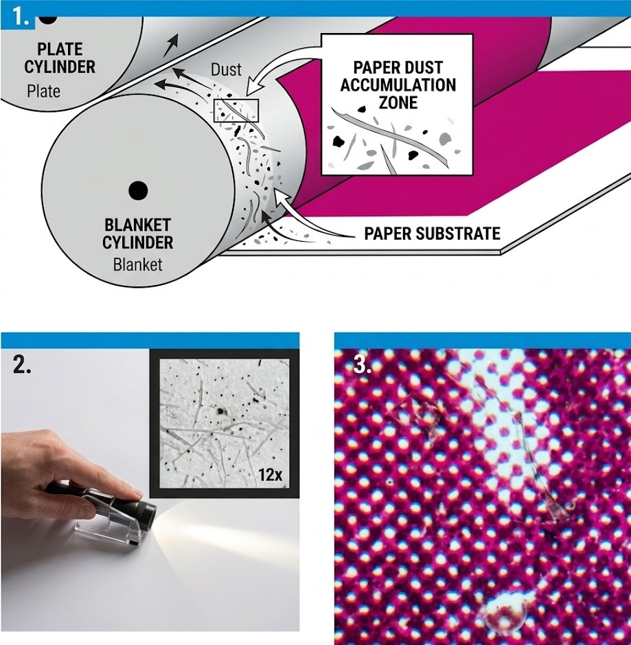
As illustrated in the technical cross-section above, the particulate matter settles in the critical nip zone between the plate and the blanket, lifting the paper substrate away from direct contact and immediately altering the geometry of the halftone dots (as shown in the magnification window).
Paper Dust Root Causes & Pressroom Emergency Remedies
To keep the press running smoothly without requiring a blanket wash every few hundred sheets, utilize this targeted troubleshooting matrix:
| Defect Manifestation | Primary Root Cause | Immediate Pressroom Corrective Action |
| Random pinhole voids or dark specks in halftone screens | Microscopic slitter dust or loose cellulose fibers resting on the sheet surface. | Stop the press, wash the blanket, and wipe the cut edges of the paper stack with a specialized tack cloth or a cloth dampened with a light glycerine solution. |
| Rapid blanket contamination within short runs | Poor dull knife quality during guillotine trimming or sheeting operations. | Inspect all four edges of the paper pile for rough, fibrous cut quality. If severe, re-trim the entire paper stock on all four sides by taking a clean 2mm to 3mm shave off the edges. |
| Severe dust buildup on the first down color unit | High static electricity attracting ambient pressroom dust or heavy paper linting. | Utilize an idle, blank printing unit at the front of the press sequence to “pre-dust” the stock on impression before it reaches the first active ink train. |
Deep-Dive Technical Analysis: Substrate Mechanics and Edge Conditioning
1. The Mechanics of Slitter and Guillotine Cut Quality
When paper rolls are converted into sheets, the sharpness and angle of the slitter knives are paramount.
A dull or improperly aligned blade does not cleanly cut the paper; instead, it fractures and crushes the coating and underlying fibers along the edge.
When the press sheet goes through the printing unit, the mechanical pull of tacky ink strips these fractured fibers completely off the edge, introducing massive amounts of debris into the ink train.
Preventative Protocol:Always perform a ‘thumb test’ along the sides of a fresh paper pallet.
If your thumb picks up a white, powdery residue, the batch has high slitter dust.
Re-trimming the edges on a sharp pressroom guillotine is required to create a clean, sealed edge profile.
2. Utilizing Pre-Dusting Units on Open Impression
If you are running a multi-color press (such as a 5-color or 6-color press) and have an open, non-printing unit available at the front of the color sequence, you can configure it as a dedicated pre-dusting system.
By running the dusty paper through this first blank unit on standard impression squeeze—either running completely dry or utilizing a minimal, clean water film through the dampening system—the blanket acts as a mechanical trap, capturing loose surface lint before the sheet ever encounters high-tack ink.
This process extends your active printing blanket wash intervals by up to 400%.
3. Ambient Controls and Edge Wiping with Glycerine
Micro-level pressroom climate controls play a passive but vital role in dust mitigation.
Low relative humidity (below 40%) increases static surface charges on the paper, causing it to hold onto slitter dust like a magnet.
Maintain pressroom parameters at 45% to 55% RH to allow static dissipative discharge.
For immediate relief during an active production run, operators can manually treat the sides of the paper stack.
Wiping the cut edges with a highly diluted glycerine-moistened rag or a specialized sticky tack cloth binds the loose fibers together, preventing them from flying into the feeder mechanism or getting pulled into the nip matrix.
What Causes Mechanical and Chemical Ghosting in Offset Printing, and How Do You Eliminate It?
Ghosting is a complex lithographic defect where unwanted phantom images, “stencils,” or silhouettes of a design element duplicate themselves across a printed solid or halftone zone.
True ghosting is divided into two types: mechanical ghosting (caused by ink starvation or localized ink accumulation on the form rollers during repeated passes over the plate cylinder) and chemical ghosting (a gas-ghosting phenomenon linked to uneven ink oxidation and drying dynamics on the pile).
Troubleshooting Offset Ghosting and Stencil Images
Ghosting can be aggressively mitigated by optimizing prepress layout and maintaining proper roller dynamics.
Use this technical matrix for an immediate pressroom fix:
| Defect Manifestation | Primary Root Cause | Immediate Pressroom Corrective Action |
| Faint light or dark phantom shapes in solid zones (Mechanical) | Ink form rollers fail to replenish their ink film during a single revolution due to a demanding job layout. | Engage or increase the oscillation stroke of the ink rollers. If impossible mid-run, adjust the ink-water balance or rotate the job layout 90 degrees on the plate. |
| Inadequate solid coverage / transparent shapes | The active ink film thickness is too thin, or the ink pigments lack sufficient chemical opacity. | Consult your ink manufacturer to reformulate the batch for higher pigment concentration/opacity, allowing you to run a thicker film without causing dot gain. |
| Streaks and irregular stencil outlines | Hardened, glazed, or poorly adjusted ink form rollers failing to transfer a uniform ink layer. | Stop the press and deep-clean the roller train. Apply a specialized regenerating wash paste to remove calcium/lime deposits. Replace rollers showing “trumpet-shaped” edges. |
Deep-Dive Technical Analysis: Mechanical Starvation and Roller Regeneration
1. Imbalance in Prepress Layout and Mechanical Ink Starvation
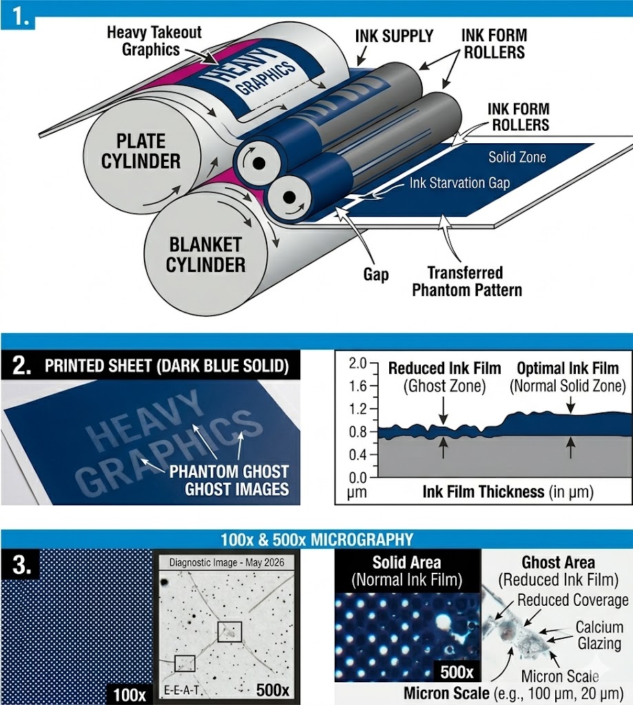
Mechanical ghosting typically occurs when a large solid area is positioned directly in line with a heavy-takeout design element (like a thick bar or large typography) relative to the print direction.
As the ink form rollers pass over the heavy-takeout element, they are stripped of ink.
When they continue their revolution onto the next solid area, they don’t have enough time to pick up a fresh, uniform film layer from the oscillator rollers, leaving a lighter “starvation” ghost image.
The Prepress Remedy:The most effective cure happens at the layout phase.
Whenever possible, place solid clear blocks at the lead edge of the plate, and position heavy graphic elements in a staggered formation.
Adding scrap ink-takeout bars (color bars) in the trim areas helps draw a continuous, even stream of ink across the entire width of the ink train.
2. Macromolecular Roller Glazing and Calcium Carbonate Removal
Over time, the continuous interaction between alkaline fountain solutions, paper dust, and ink components creates a microscopic, glass-like layer on the rubber rollers.
This is known as “roller glazing”.
Glazed rollers lose their dynamic friction coefficient and can no longer hold or transfer an ideal ink film thickness (which should ideally measure between 1.0 and 1.4 microns for conventional offset).
Maintenance Protocol: Standard daily solvents only remove surface ink; they do not dissolve glaze or calcium/lime deposits.
Implement a strict weekly maintenance routine: apply an acidic calcium-removing wash paste to the roller train and let it idle for 10 minutes before rinsing.
This open chemical wash regenerates the synthetic elastomer pores, restoring the rubber’s original ink-receptive properties.
3. Elastomer Hardness and Trumpet-Edge Deformations
As nitrile or polyurethane rollers age under thermal and chemical stress, their plasticizers leach out, causing the elastomer to harden.
Check your rollers using a durometer gauge.
Standard offset ink form rollers should maintain a hardness between 25 and 30 Shore A.
If a roller exceeds 35 Shore A, the rubber loses its elasticity.
Under mechanical nip pressure, the outer edges of a hardened roller will bulge out in a distinctive “trumpet shape.”
This causes intense friction and localized abrasion against the plate bearers, resulting in extreme ink accumulation at the edges and severe ghosting.
Hardened rollers cannot be regenerated and must be fully replaced to guarantee a uniform 3mm to 4mm contact stripe.
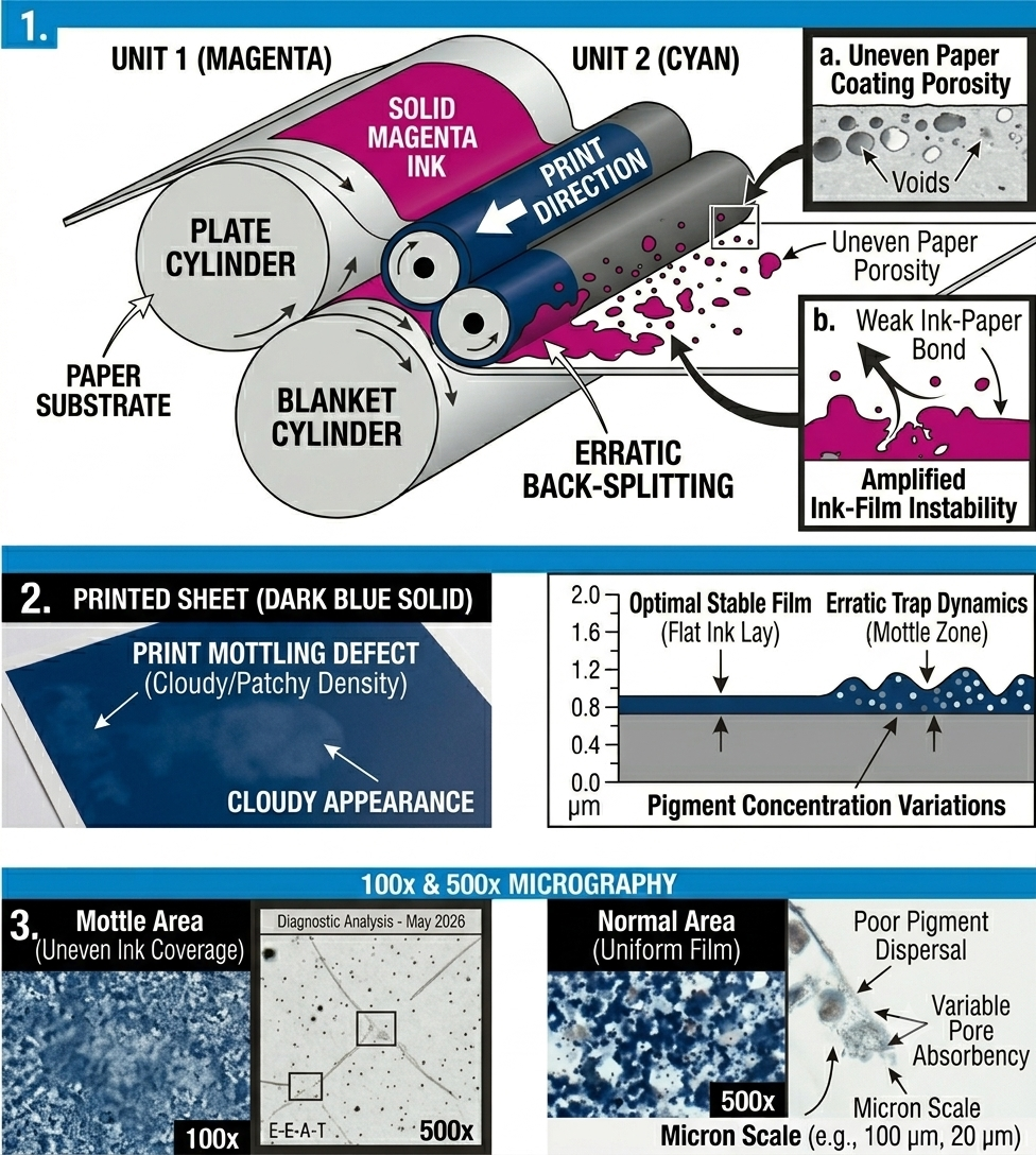
What Causes Print Mottling and Cloudy Solids in Offset Printing, and How Do You Fix It?
Print mottling (often described as a cloudy, blotchy, or uneven print appearance) is a complex lithographic defect characterized by random, non-uniform ink density variations across solid image zones or heavy halftone tints.
Based on over 25 years of industrial print analysis, mottling is rarely caused by a single variable.
Usually it is one dynamic interaction involving non-uniform substrate absorbency, improper ink-trapping physics, and subsequent back-splitting across downstream blanket cylinders in multi-color sheetfed offset presses.
Troubleshooting Print Mottling & Density Variations
Mottling can be systematically diagnosed by isolating substrate structural uniformity from press chemistry.
Use this technical matrix for an immediate floor evaluation:
| Defect Manifestation | Primary Root Cause | Immediate Pressroom Corrective Action |
| Cloudy, patchy solids appearing predominantly on multi-color jobs | Non-uniform paper stock absorption causing uneven ink penetration and erratic back-splitting on subsequent blankets. | Adjust the ink tack sequence. Reduce the tack of downstream inks using a compatible gel reducer to ease the split tension, or consult the paper mill for a more uniform coating base. |
| Banded or localized density variations across the sheet | Improper or uneven impression cylinder pressure, or a structurally fatigued (worn) blanket. | Check cylinder packing and optimize blanket-to-impression squeeze to an exact window of 0.10mm to 0.12mm. Replace the printing blanket if it shows low micro-elasticity. |
| Striated or uneven ink lay within individual color zones | Glazed, hardened, or improperly set form rollers failing to distribute a continuous ink film. | Re-set ink form-to-plate roller stripes to a precise width of 3mm to 4mm. Apply a deep-cleaning wash paste to eliminate micro-level surface glazing. |
Deep-Dive Technical Analysis: Back-Splitting Physics and Emulsification Limits
1. The Phenomenon of Substrate Absorbency and Dynamic Back-Splitting
In a standard 4-color sheetfed offset configuration, when the first down ink is applied to the paper, it requires uniform and immediate vehicle penetration.
If the paper’s coating layer exhibits localized variations in binders or porosity (cloudiness in the coating), the ink will absorb unevenly.
As this freshly printed, un-dried ink layer passes through the second, third, and fourth printing units, it comes into direct contact with the subsequent rubber blankets.
During each impression cycle, a percentage of the underlying ink film is pulled off and splits back onto the downstream blanket—a process known as back-splitting.
If the initial penetration was uneven, the back-split forces will aggressively amplify these structural variations, transforming micro-level absorption differences into a highly visible, blotchy “cloudy printout.”
2. Managing Ink Rheology and Fountain Solution Emulsification Limits
An incorrect ink/water balance heavily exacerbates trapping and trap-induced mottle.
When a press operates with an excessive volume of dampening water, or if the fountain solution chemistry causes over-emulsification, the ink’s structural cohesive strength drops.
The waterlogged ink begins to separate erratically within the nip zone.
The Operational Fix:Tighten the dampening window to maintain a minimum stable water film.
Ensure that your ink tack sequence is tightly controlled via Inkometer metrics, making sure that subsequent colors possess a lower tack profile to prevent them from mechanically lifting or disturbing the fragile ink layer beneath.
3. Mechanical Nip Geometry: Roller Squeeze and Blanket Elasticity
Defective press components often turn a minor paper-absorbency issue into a catastrophic print rejection.
Worn or chemically fatigued blankets lose their structural “smash resistance” and dynamic rebound speed, resulting in localized pressure drops across the impression zone.
Always verify packing sheets using a micrometer gauge to guarantee true rolling line speeds.
Furthermore, inspect the ink form rollers: if the rubber has aged beyond 30 Shore A hardness, it will bounce and skip microscopically across the plate cylinder.
Re-adjusting the roller stripes to a uniform 3mm to 4mm contact path ensures a smooth, uniform shear rate, allowing the ink film to distribute flatly before substrate contact.
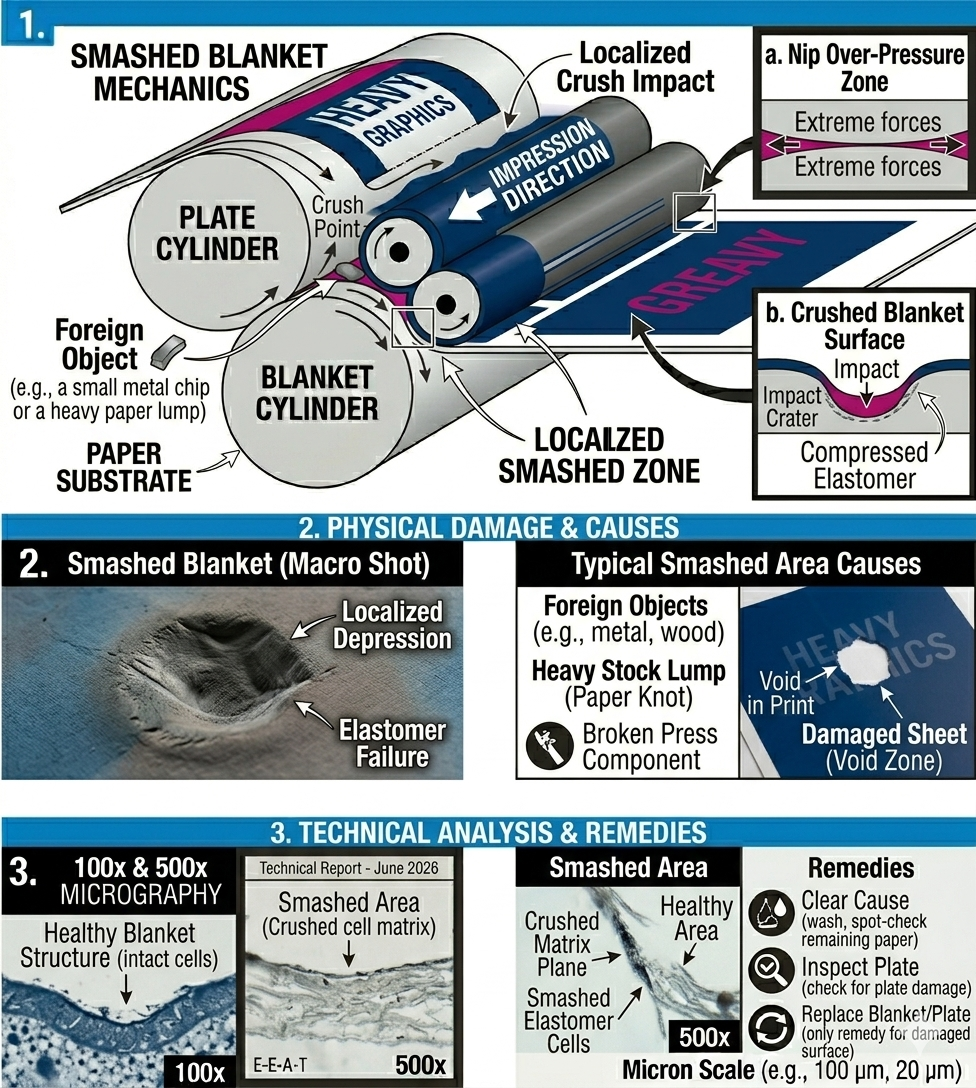
What Causes Smashed Blanket and Why Is Replacement the Only Solution?
Smashed blanket (or localized elastomer collapse) is a permanent mechanical failure in the pressure zone of an offset press.
This phenomenon occurs when localized compression, which exceeds the limits of micro-regeneration of the compressible layers, destroys the cellular matrix of the blanket.
Drawing on years of failure analysis, we know that unlike temporary compaction, a smashed area results in a physical, irreversible depression that creates a sharp density void or color crater in the printed sheet, often repeating at precise intervals (corresponding to the blanket cylinder circumference).
| Defect Manifestation | Primary Root Cause | Immediate Pressroom Corrective Action |
| Random repeating voids or unprinted patches with repeating intervals (Donut shape) | Dynamic compaction of a large, hard particle (skin specks, metal flecks, or hard paper lumps). | Stop the press immediately. Wash blanket to find the contaminant. Verify packing sheets. If the physical depression remains after washing, replace the blanket. |
| Repeating dents / concentric circles on blanket and sheet | Cumulative compaction on old, chemically fatigued blankets (hardness over 35 Shore A). | Implement a strict weekly maintenance protocol to eliminate cumulative contamination. Apply washpaste with calcium remover. If hardness exceeds standard, replace the blanket. Optimize the blanket-to-impression squeeze. |
| Repeating halo or density drop-off in halftones screens | Contaminant compactly lodged and obstructing dots transfer. | Wash blankets across all units. The contamination must be removed before dynamic redeposition occurs. Utilize a fountain solution formulated with higher sequestering capability. |
Deep Technical Analysis: Mechanics of Localized Compressive Collapse
1. Nip Zone and Irreversible Cellular Compression
A standard compressible offset blanket is designed to operate within a precise compressive range (typically between 0.10mm and 0.12mm for optimal printing).
The micro-pores or closed cells in the compressible layers are capable of rapid rebound.
However, when a foreign object (metal object, bolt, screw, or hard paper lumps) enters the nip zone, localized compression can reach over 0.25mm+.
This extreme stress crushes the elastomeric matrix itself.
Technical Definition: The cells collapse, resulting in a permanent physical depression (depression set).
Because the blanket surface is no longer flat, it no longer physically contacts the paper, leaving a white gap.
2. The Role of Shore A Hardness and Rubber Age
Old, chemically aged rubbers with increased hardness (over 35 Shore A) are much more sensitive to crushing.
The elastomer loses its natural elasticity (rebound speed) and cohesive strength.
Even a small paper defect, which a new, compressible rubber would absorb, can cause permanent depression in an old rubber.
3. Remediation and Thorough Inspection Protocol
Operational Protocol:Rubber cleaning should only be done to identify the exact cause (for example, a bolt that has fallen out of the machine or paper lumps from a paper spool).
If the exact cause is not removed, the new rubber will crush on the first rotation.
Also, an inspection of the printing plate is mandatory, since hard objects often damage both cylinders (rubber and plate).
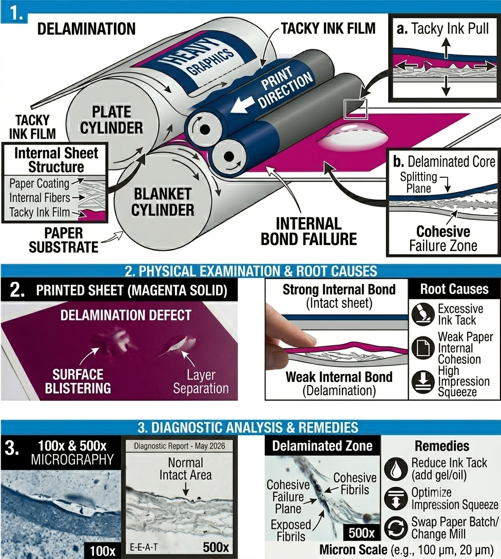
What Causes Paper Delamination and Sheet Splitting in Offset Printing, and How Do You Prevent It?
Paper delamination is a catastrophic structural failure within the substrate where the internal bonding strength (Z-direction tensile strength) of the paper fibers cannot withstand the out-of-plane splitting forces (ink tack and nip shear) encountered within the printing nip.
When these cohesive forces fail, the sheet physically splits into distinct layers, causing surface blistering, complete surface tearing, or the problematic wrapping of the delaminated layer around the blanket cylinder.
Troubleshooting Paper Delamination & Cohesive Failure
Delamination indicates a severe mismatch between ink rheology and paper structural integrity.
Use this technical matrix for an immediate pressroom evaluation:
| Defect Manifestation | Primary Root Cause | Immediate Pressroom Corrective Action |
| Surface blistering, bubble formation, or complete sheet splitting | The internal bond strength of the paper (Scott Bond Value) is lower than the split-tack pull force of the ink. | Stop the press immediately. Wash blankets. Reduce the ink tack on the problem unit by adding 1% to 3% compatible reducing oil or gel varnish to the fountain. |
| Severe delamination on multi-color units (e.g., Units 2, 3, or 4) | Incorrect ink tack sequence; subsequent colors have higher tack than the first-down color, aggressively picking the substrate. | Verify and correct the ink tack sequence. Ensure that later-down colors have a lower Inkometer tack value than the previously printed layers to facilitate flawless trapping. |
| Localized delamination along solid graphics or heavy tints | Excessive mechanical impression “squeeze” on a specific unit creating localized shear forces. | Re-set and optimize the blanket-to-impression cylinder squeeze to a precise window of 0.10mm to 0.12mm. Verify cylinder packing specs with a micrometer. |
Deep-Dive Technical Analysis: Substrate Mechanics and Rheological Controls
1. The Scott Bond Metric and Internal Cohesion (Z-Direction Strength)
The most fundamental variable in delamination is the paper’s Z-direction internal bond strength, often measured using the Scott Bond test (TAPPI T 569).
Modern, fast-setting offset inks often have high inherent tack to ensure sharp dot transfer.
If a paper mill utilizes insufficient binders (such as starch or latex) within the fiber matrix, the paper has weak cohesive integrity.
Preventative Action: If delamination persists despite optimizing ink and press parameters, you must isolate the paper batch and contact the manufacturer to swap production runs for stock with a higher guaranteed internal bonding specification.
2. Dynamic Nip Rheology: Managing Multi-Color Tack Sequences
In a standard 4-color sheetfed offset configuration, controlling the ink tack sequence across units is vital.
The first-down ink must have the highest tack, with each subsequent unit utilizing an ink with a step-down of at least 1 to 2 tack units.
If this sequence is incorrect (e.g., if the magenta on Unit 3 is tackier than the cyan on Unit 1), the subsequent ink will physically pull and disrupt the fragile ink layer and paper surface beneath it.
This mechanical stress causes immediate cohesive failure within the weakened paper structure.
3. Optimizing Mechanical Impression Squeeze and Cylinder Packing
Mechanical over-pressure is a major catalyst for delamination.
Excessive squeeze between the blanket and impression cylinders—often caused by over-packed blankets or incorrect pressure settings—significantly increases the instantaneous shear forces exerted on the sheet in the nip zone.
Always use a micrometer to verify packing sheet thickness against the press undercut specifications.
Dropping the impression squeeze by even a small increment (e.g., from 0.15mm to 0.10mm) can drastically reduce the Z-direction forces, often allowing a marginal paper batch to successfully run without splitting.
Frequently Asked Questions: Advanced Offset Press Troubleshooting & Lithographic Physics
Q1: What is the primary difference between Mechanical Ghosting and Chemical (Gas) Ghosting?
A: The distinction lies in the root cause mechanism.
Mechanical Ghosting is an immediate phenomenon caused by ink starvation or accumulation on the ink form rollers, failing to replenish a uniform film due to demanding prepress layouts.
Chemical Ghosting (Gas Ghosting) is a delayed post-press phenomenon occurring in the pile, caused by uneven oxidation and dynamic drying rates between back-to-back printed sheets, resulting in a matte or glossy stencil image.
Q2: How does incorrect Ink/Water balance exacerbate Print Mottling?
A: An unstable ink/water balance directly impacts ink rheology and trapping.
Excessive dampening solution causes severe emulsification, lowering the ink’s cohesive strength.
As the waterlogged ink passes through downstream units, this weakened structure separates erratically during back-splitting, amplifying micro-level paper absorbency variations and transforming them into visible cloudy density fluctuations (mottling).
Q3: When troubleshooting Paper Delamination, which key press metric should be optimized first?
A: The most critical immediate optimization is reducing the ink tack sequence.
If subsequent colors possess a higher tack (Inkometer value) than the first-down color, the dynamic out-of-plane splitting forces exceed the paper’s internal Z-direction bonding strength (Scott Bond Value).
Lowering the ink tack using compatible gel varnish, followed by reducing impression cylinder squeeze to a precise 0.10mm to 0.12mm window, will typically eliminate substrate splitting.
Q4: What are the diagnostic indicators that a printing blanket is “smashed” versus merely contaminated?
A: A contaminated blanket (e.g., with paper dust or hickeys) will typically present irregular or repeating voids that can be washed away with solvent, restoring the micro-topography.
A smashed blanket, however, is a catastrophic mechanical failure resulting in a physical depression crater.
Even after thorough cleaning, the damaged area shows a repeating void with concentric density rings due to the collapsed cellular matrix and irreversible elastomer hysteresis.
A micrometer gauge or packing gauge is required to confirm the physical depression depth.
More on-press troubleshooting’s and their solution you may find here: